The scope is clickable & draggable. More here.
Note: The simulator is not compatible with Internet Explorer 11 and below. Please use Chrome/Firefox/Safari instead.
Note: The simulator is not compatible with Internet Explorer 11 and below. Please use Chrome/Firefox/Safari instead.
How to run the simulation
- There are two individual circuits with different resistor loads - a) 100 ohm and b) 50 ohm
- Hit the "Run" button and observe the system response for both systems
- Modify the capacitor and resitor values to observe the effect on dynamic response
- Scopes 1/3 are capacitor voltages. Scopes 2/4 are resistor currents
Theory
Resistive Discharge
- The basic premise is very simple - resistor draws current from a voltage source connected across its terminals.
- Resistor current is proportional to voltage. The higher the voltage the higher the current. The ratio of voltage to current is called resistance and is measured in ohms.
- The initial capacitor voltage in the simulation above is 100 V. The capacitance is 1 mF.
- The resistance of the first circuit is 100 ohms. Hence, the time constant is:
$$\tau = RC = 100 \Omega \times 1e-3 F = 0.1 s$$ - The resistance of the second circuit is 50 ohms. Hence, the time constant is:
$$\tau = RC = 50 \Omega \times 1e-3 F = 0.05 s$$ - These values are nicely supported by the simulation. Please do change the capacitor and/or resistor values to see the effect.
From Circuit to Block Diagram
- Both the circuit and signal block diagrams are shown below:

- The output of the summing junction is the net capacitor current. Since there are no other elements that would charge or discharge the capacitor aside the resitor, the first input is set to 0A.
- The relationship between capacitor current and voltage is as follows:
$$v_{(t)}= \frac{1}{C}\int i_{(t)} dt$$ - After taking the Laplace Transform:
$$V_{(s)}= \frac{I_{(s)}}{Cs}$$ - Hence, the input of 1/Cs block is capacitor current and the output is capacitor voltage.
References
- (CSA) System Modeling With Transfer Functions.
- (CSA) Control System Block Diagram.
- (CSA) System Dynamics - Time Constants.
- (CSA) Web-based Simulator Documentation.
Additional Notes
- The resistor eventually dissipates all the capacitor energy. The final cap voltage will be 0 V.
- Since the power dissipated in the resistor is R*i(t)*i(t), the initial power could be fairly high. Thermal considerations need to be made.
- These circuits are commonly used in the industry.
Version
Version of this article is 04/20/2018.
Further Reading

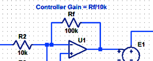
Proportional Controller Implementation
In MatLab, DSPs, and FPGAs.
.

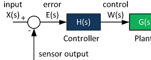
Control System Block Diagram
The fundamentals of signal flow.

System Modeling With Transfer Functions
Introduction to dynamic systems.

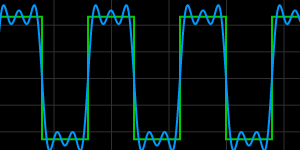
Fourier Series Demo
It is all sine waves.
Please leave us a comment regarding the content at this page.