Digital Control Loops
Table of Contents
What are time constants and where are they found?
The figure below shows the most fundamental feedback digital control system, which is a more complicated version of a purely analog control system. It contains a plant (typically a physical system that we would like to control), a digital controller, an analog to digital converter (A/D), which changes a voltage or current signal into a digital form (number), a digital to analog converter (D/A), which changes a digital signal (number) into a voltage or current signal, an actuator, which implements the control action, and a summing junction that determines the error between the actual and commanded values. The feedback sensor is represented by its own transfer function as well.
Virtually all modern advanced control systems closely follow the figure below.
Hover over the figure for more details.
Detailed Explanation
The system signals are described in more detail here:
1) Response, R(s) = Y(s) Gsens(s)
- First, the output of a system is measured with a sensor, whose response is typically proportional to the measure signal.
- This signal is the output of the sensor. Virtually all feedback signals are measured and scaled by sensors, such as pressure sensors, voltage and current sensors, torque meters, etc. Sometimes, the sensor dynamic is very fast and such the sensor transfer function can be neglected. In such case, Gsens(s) = 1. However, very often it is the sensor bandwidth that limits the bandwidth of the overall system.
- E.g, voltage and current sensors typically have a high bandwidth (tens of kHz for current sensors and units of kHz for voltage sensors).
- E.g, temperature sensors do have their own thermal constants and tend not to immediately respond to an abrupt temperature change.
2) A/D
- The measured response is converted to digital form by an analog to digital converter. The converter is either a part of a processor or an external IC. Once that conversion takes place, the signal is in the digital part of the loop - shown in blue.
3) Error signal, E(z) = X(z)-R(z)
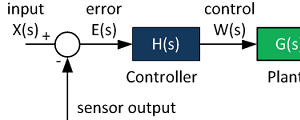
- Error is the output of the summing junction and is the input to the feedback controller. Note that the error is the difference between the desired and actual responses.
4) Controller, H(z)
- The feedback controller applies a control law to the error signal. There are many basic compensators available (proportional, proportional-integral, lead-lag). Since the controller is digital, special discrete-time controllers can be employed as well (such as a dead-beat controller).
5) D/A
- Once the control signal has been computed, the control effort is applied to the actuator by converting the digital signal to an analog voltage using a digital to analog converter.
6) Actuator.
- The actuator is a device that takes the controller output and applies it to the controlled system (the plant).
- The actuator might be a motor controller (drone rotor), position controller (robot arm), or even a audio speaker.
7) The plant, G(s)
- This is the system we aim to control (drone position, altitude, tram wagon velocity, MRI magnetic field)
Simulink Example
The figures below show all signals for a simple system - compare the waveforms with a fully analog system: Control System Block Diagram.
Plant - an analog-domain single pole system with 1 rad/s bandwidth.

Controller - a discrete-time proportional controller with gain of 5.

Sensor - an analog-domain single pole system with 10 rad/s bandwidth.

Simulink model and results are shown below.


References
This page is a modification of a now non-existent page located at:
http://www.facstaff.bucknell.edu/mastascu/eControlHTML/Intro/IntroNotes/IntroNote_VeryBasic_DigContLoop.htm
Version
Version of this article is 10/9/2017.
Further Reading

Proportional Controller Implementation
In MatLab, DSPs, and FPGAs.
.

Control System Block Diagram
The fundamentals of signal flow.

System Modeling With Transfer Functions
Introduction to dynamic systems.

Fourier Series Demo
It is all sine waves.