The scope is clickable & draggable. More here.
Note: The simulator is not compatible with Internet Explorer 11 and below. Please use Chrome/Firefox/Safari instead.
Note: The simulator is not compatible with Internet Explorer 11 and below. Please use Chrome/Firefox/Safari instead.
How to run the simulation - 3 steps
- There are two individual systems with different preloaded loads - a) with no damping and b) with damping
- Hit the "Run" button and observe the system response for both systems
- Modify the proportional gain to observe the effect on steady-state error and dynamic response
Theory
One step beyond On-Off systems
- The proportional controller is the simplest linear controller - linear since the output is linearly proportional to the input of the controller.
- Look at the block below - the input to the proportional controller is the difference between the desired output and the actual output.
- The larger the difference, the larger the force the controller commands as it tries to correct for the error.
- If there is no error, the output of the controller is zero.

On the dynamics of Proportional Controllers
- The plant in the simulation is of first order. Since the controller is not dynamic (it does not integrate or differentiate), the overall system order is 1 as well.
- First-order system do not oscillate or experience overshoot.
- Increasing the controller gain makes the system more aggressive:
- It will track much better than systems with low gains.
- Also, it will track the reference much faster.
- If there is damping in the system (second example), a gain increase will reduce the steady-state error. However, the error will never come down to zero without an integrator in the controller or another compensation technique, such as virtual reference decoupling.
- This is typically not a problem for first order systems; however, an increase of gain can quickly destabilize higher order systems.
Driving Current Through an Inductive Load
- E.g., through motor windings, an inductive heating element, or an MRI coil
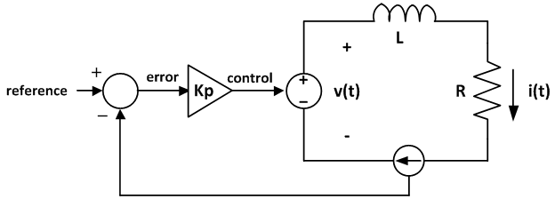
- The proportional controller sets the output voltage of an amplifier.
- The amplifier applies voltage across a coil L with parasitic resistance R
- In steady-state, the coil voltage is:

- Coil voltage is equal to the amplifier voltage:

- And the output of the controller is:

- Rearranging terms to obtain the ratio of coil current to the reference current:
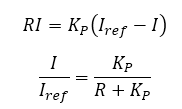
- Hence, with no parasitic resistance (R = 0 Ohm), the coil current always perfectly follows the reference current! Note that is only happens in steady-state. See the SYSTEM MODELING WITH TRANSFER FUNCTIONS article to learn more about system dynamics.
- Alas, the parasitic resistance is virtually never zero. Hence, the proportional controller cannot achieve zero steady-state error.
- However, if the ratio of Kp to R is reasonably high (say 10:1), the steady-state error is small (below 10%).
- In other words, small gains produce inaccurate systems.
References
This page is a modification of a now non-existent page located at:
http://www.facstaff.bucknell.edu/mastascu/eControlHTML/Intro/IntroNotes/IntroNote_VeryBasic_PropCont.htm
Version
Version of this article is 10/02/2017.
Further Reading
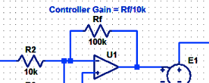
Proportional Controller Implementation
In MatLab, DSPs, and FPGAs.
.
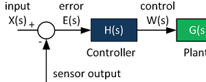
Control System Block Diagram
The fundamentals of signal flow.
System Modeling With Transfer Functions
Introduction to dynamic systems.
Fourier Series Demo
It is all sine waves.
Please leave us a comment regarding the content at this page.