Note: The simulator is not compatible with Internet Explorer 11 and below. Please use Chrome/Firefox/Safari instead.
Load scenario:
- Lead controller (Lead controller increases phase margin / reduces overshoot)
- Lag controller (Lag controller increases low-frequency gain)
How to run the simulation - 3 steps
- There are two preloaded scenarios: lead/lag compensator - select one
- Hit the "Run" button and observe the system response for both systems
- Modify the compensator gains to observe the effect on steady-state error and dynamic response in both time-domain and frequency-domain
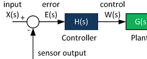
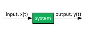
Control System

The purpose of control system for a plan is to improve the following characteristics of the system
- Improve gain or bandwidth
- Improve stability.
- Track complex reference signals (periodic or non-linear)
There are various types of compensators that achieve these objectives in a feedback control system. Two common types of compensators are lead and lag compensators. Both the compensators introduce a pole and a zero the system. The transfer function of the compensator takes the form of:
In this article the lead and lag compensators will be briefly discussed.
Lag Compensation
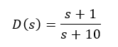
The compensator can be defined as a lag compensator if a > p. In a lag compensator, the low frequency gain is increased and this helps reduce the steady state error. The typical bode plot of a lag compensator is as shown below for an example compensator of:
It can be observed that at low frequencies the compensator has a high gain and the magnitude at high frequencies is insignificant. Thus, this type of compensator reduces the steady state error without affecting the high frequency transients.
Key fact about the compensator: The lag/lead compensator provides maximum lag near the center frequency but this corner (= center) frequency needs to be placed below the new gain cross-over frequency. The corner frequency is sqrt(a * p).
- Determine the factor by which the steady state error constant must be increased for satisfactory steady state error.
- Place the compensator zero at 10% of the distance between the origin and the first pole or zero on the LHP from the origin.
- Pick system gain such that the dominant closed loop pole pair before compensation is changed minimally.
- Check transient response and adjust accordingly.
The main motivation of the lag compensator is to improve the steady state error without affecting the shape of the root locus of the uncompensated system.
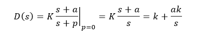
A special case of the lag compensator is the PI controller when the pole is place at the zero (i.e P=0):
For more details on PI compensation schemes, please see this article: PI Controller : Theory + Demo.
Lead Compensation
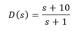
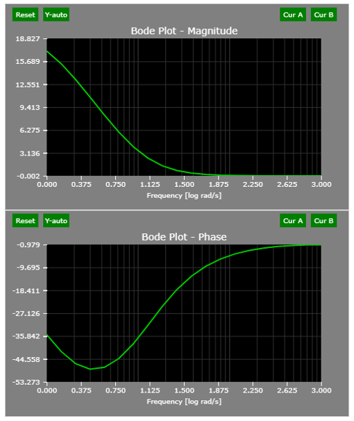
The compensator can be defined as a lag compensator if p > a. The compensator improves the transient performance of the system as it affects the high frequency components significantly. The typical bode plot of a lead compensator is as shown below for an example compensator of:
The bode plot indicates that the gain margin of the plant would be unaffected if a lead compensator is used but the phase margin would be improved. However, it is important to note that in a lead compensator as high frequency response has a high gain, noise at high frequency would also be amplified and this is an issue in a practical system and appropriate care in the sensing system must be adopted.
Add the compensator so that the closed loop transfer function has a pair of complex poles with the desired damping ratio and natural frequency.
The complex poles dominate the system response
- Determine the damping ratio for desired overshoot and resonant frequency for desired closed loop response time. Use this to identify desired pole.
- Determine the phase angle of the plant at the desired pole and place the pole such that is it 180 degrees from the plant.
- Place the zero such that the root locus has all the poles on either far left hand plane or near the zeros.
- Determine the gain to satisfy steady state error requirement.
In the design process it is key to go through step 3 several times to ensure proper overshoot. If required overshoot is not achieved after several trails, the damping ratio and resonant frequency would need adjustment.
A special case of the lead compensator is the PD controller when the zero is place at the zero (i.e A=0):
Summary
| Lag compensator | Lead compensator |
|---|---|
|
|
Tausif Husain
Version of this article is 11/2/2017.
Further Reading
Proportional Controller Implementation
In MatLab, DSPs, and FPGAs.
.
Control System Block Diagram
The fundamentals of signal flow.
System Modeling With Transfer Functions
Introduction to dynamic systems.
Fourier Series Demo
It is all sine waves.