Voltage to Current Opamp Converter
In most applications of analog electronic circuits we tend to deal with voltage signals. Voltage is rather prevalent these days. E.g., when one says dc-to-dc converter, we immediately think about voltage-to-voltage conversion. Perhaps that's due to the lack of natural current sources; many are comfortable with the notion of storing energy in a capacitor but not so much in a coil.
I'd like to share a short analysis of a voltage-to-current opamp-based conversion circuit. Say you, a design engineer, are asked to design a voltage sensor whose output voltage swing not known at this point. It is a generic sensor. Isn't it easy enough to make the output current proportional to input voltage and therefore let the user determine the voltage swing by selecting the appropriate burden resistor?
Let's take a look at the following circuit. External voltage is what we measure (could be thousands of volts); the burden resistor Rs is located on an application-specific controller board.
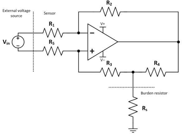
Basic rules apply (https://en.wikipedia.org/wiki/Operational_amplifier#Ideal_op-amps):
Opamp inputs do not draw any current.
Voltage between the two opamp inputs is kept at zero due to negative feedback.
Output current capability is unlimited.
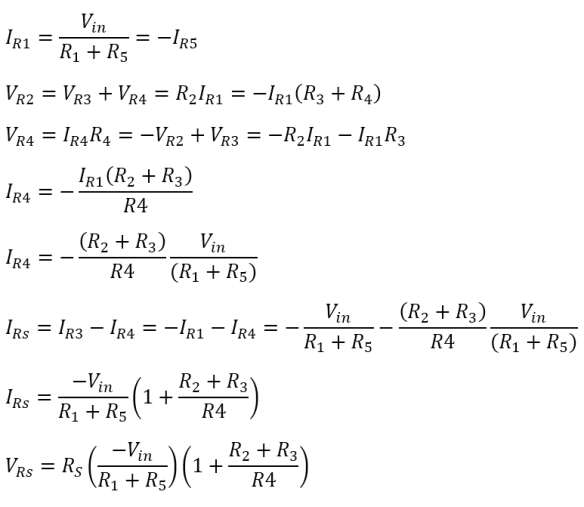
How is the sensor output current calculated? With the help of updated drawing:
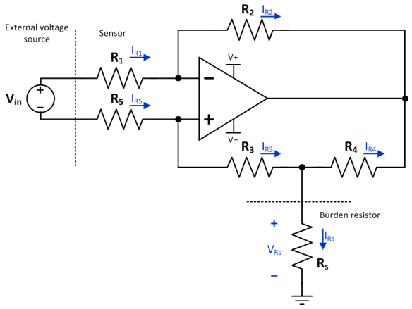
- Assume:
- Voltage between the input terminal is zero.
- Therefore, currents through R1 and R5 are equal and opposite.
- Therefore, the voltages across R2 and (R3+R4) are equal.
- Therefore, currents through R2 and R3 are determined.
- Therefore, voltage across R4 is determined.
- Therefore, current through R4 is determined.
- Therefore, current through Rs is determined. Done!
- The equations below follow the logic above.
- More thoughts:
- Input voltage would be typically scaled down using a number of series resistors and buffered with an opamp.
- This voltage sensor is not isolated, although leakage currents should be on the order of micro-amps.
- The opamp power supply should come from an external source and should be isolated.
- Zener diodes should be used throughout the system to prevent opamp saturation and voltages outside the opamp range.
- Since this is a current source, burden resistor can be zero ohms (which is not terribly useful...).
- Opamp negative feedback path should have a cap to form a low-pass filter.
Further Reading
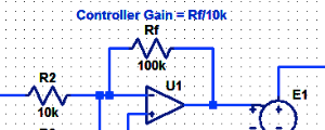
Proportional Controller Implementation
In MatLab, DSPs, and FPGAs.
.
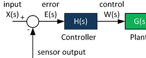
Control System Block Diagram
The fundamentals of signal flow.
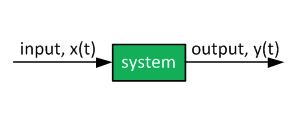
System Modeling With Transfer Functions
Introduction to dynamic systems.
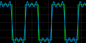
Fourier Series Demo
It is all sine waves.