Proportional Controller Implementation
Table of Contents
The following circuit produces an output voltage proportional to the difference between the Vsetpoint and Vsensor voltages.
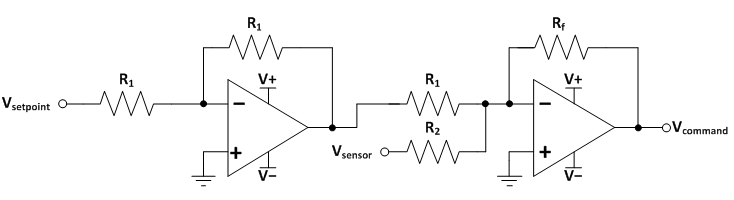
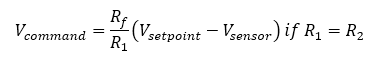
The first opamp is an inverting amplifier with unity gain.
The second opamp is an inverting summing amplifier with gain of Rf/R1.
More info about operational amplifiers can be found at the OpAmp WikiPedia page here: https://en.wikipedia.org/wiki/Operational_amplifier#Ideal_op-amps
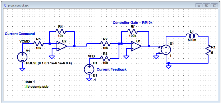
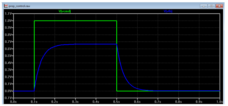
The following LTSpice simulation shows the circuit in action (the controller gain is 100 kOhm/10 kOhm = 10).
The following pseudocode can be applied to all digital signal processor and microcontrollers:
1) Determine the setpoint value Icmd
The value is typically set by user or a higher-level controller.
2) Measure the output Ifb_adc
Sample the analog feedback signal coming from a sensor with an analog-to-digital converter
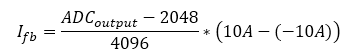
Scale the feedback signal such that it uses the same range as the command. E.g., the 12-bit ADC has output of 4095 points for the feedback sensor signal of 5V, which corresponds to inductor current of +10A. 0 points from ADC corresponds to sensor signal of 0V, which corresponds to inductor current of -10A. Thus, the ADC output has to be scaled by the following equation:
3) Calculate error Error
Error = Icmd - Ifb
4) Compute the control signal value Output
Output = ProportionalGain * Error
5) Output the control signal using digital-to-analog converter, pulse-width-modulation, or other means.
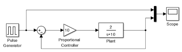
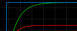
The diagram below shows a plant transfer function with DC gain of 0.5 and a single pole at 10 rad/s. The transfer function is an accurate depiction of the inductance-resistance circuit shown in the Analog Implementation section.
It is exceedingly easy to simulate dynamic systems in Simulink, which is a combination of a powerful GUI and various time-domain solvers that make sure all dynamics of modeled systems are captured carefully.
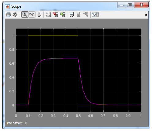
The plot below shows the current command (yellow) and inductor current (purple).
The FPGA implementation closely follows the same steps as the DSP Implementation.
However, the major difference is the parallel nature of FPGA code.
Code in a DSP (typically written in the C-language) is executed sequentially.
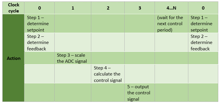
However, code in FPGA is executed in parallel. Therefore, if the control action is to occur at a specific rate, the way to achieve the proper behavior is to place a time delay between the steps as highlighted below. Note that Steps 1 and 2 can be executed in parallel since the signals are not depedent on each other.
Further Reading
Proportional Controller: Theory and Demo
Is there really a steady-state error?
.
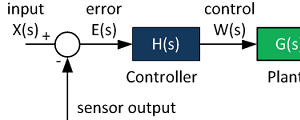
Control System Block Diagram
The fundamentals of signal flow.
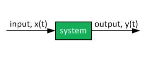
System Modeling With Transfer Functions
Introduction to dynamic systems.
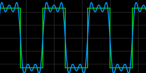
Fourier Series Demo
It is all sine waves.