A Quick Look on Three-phase Overmodulation Waveforms
Three-phase PWM power converters are mainly used either as motor drives or wind/solar inverters connected to the electrical grid. Other applications are FACTS, STATCOMs, dual-active bridges, DFIGs, etc.
In all cases, there is a three-phase voltage source connected through some impedance, which is typically inductive. To control the power flow it is required to control phase currents; and such our voltage-source converter behaves as a controlled current source. There are many practical limitations, the one we will discuss today is the voltage modulator.
The purpose of a voltage modulator is to translate the digital voltage reference into PWM signals. Obviously, PWM modulator is a non-linear element, since the instantaneous output voltage is saturated either at -Vdc/2 or at Vdc/2 (or at Vdc or 0 V). The average output voltage is, however, a linear function of the duty ratio and many times we use the averaged model approximation to speed up simulations. PLECS (an excellent simulation tool for power electronics) also offers both switched or averaged modeling. Output voltages of any inverter are limited in magnitude by the available DC link voltage. Linear region is typically extended by employing one of the many forms of 3rd harmonic injection or by Space-Vector Modulation.
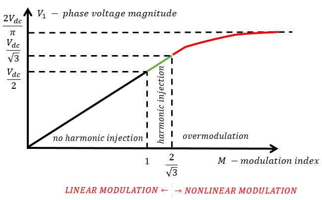
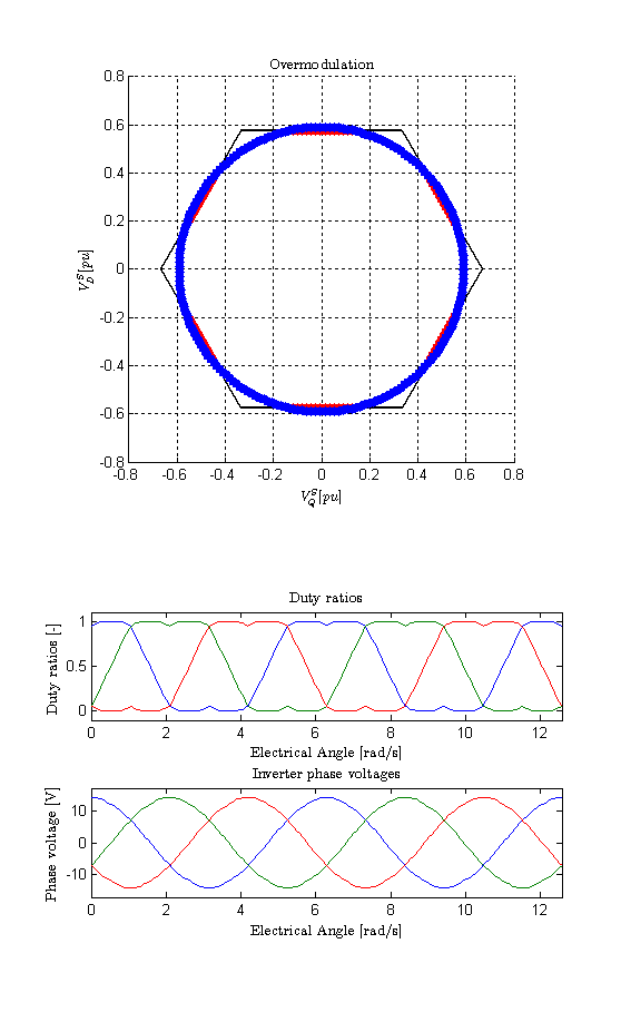
The figure below is a one-slide summary of modulation limits. The hard stop is the six-pulse commutation since that is the maximum voltage a three-phase power converter can generate. Linear region waveforms have very low harmonic distortion, mainly with some harmonics clustered around the switching frequency. On the other hand, overmodulation results in major low-frequency harmonic distortion.
In terms of control theory, any kind of saturation in the control or physical system path will cause the physical system to run in a virtually open-loop manner. This could be very dangerous, of course, in terms of losing instantaneous current control. IGBTs and MOSFETs do not have a great overcurrent capability like SCRs tend to have. The non-linear modulation region (called overmodulation) is typically not used in grid-connected systems since grid current must have a low total harmonic distortion but is sometimes used in motor drives where harmonic current just increases the torque ripple. Motors also have much larger impedance than grid.
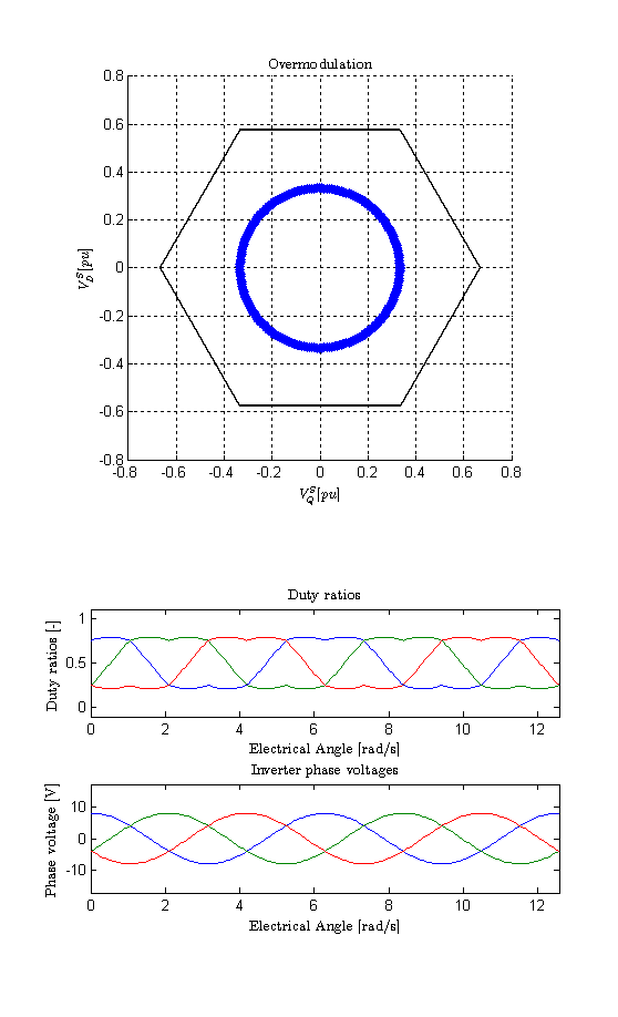
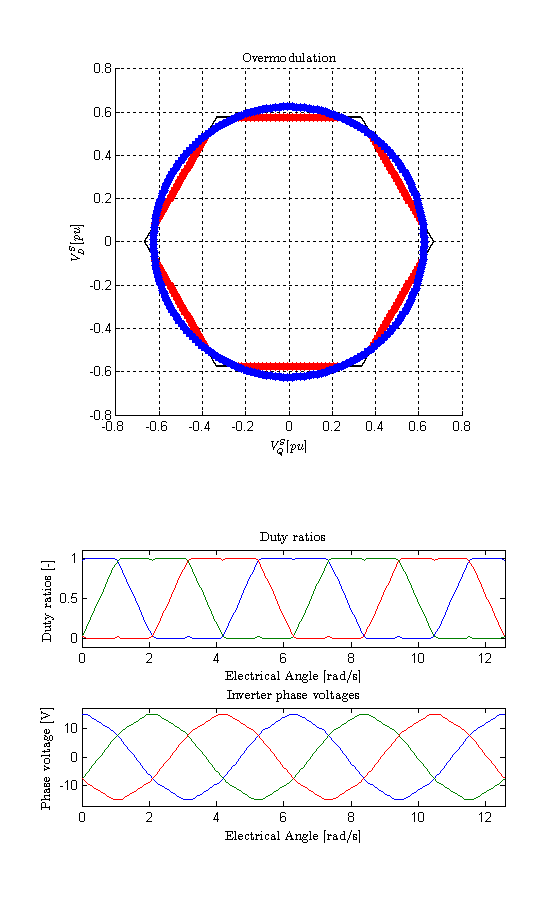
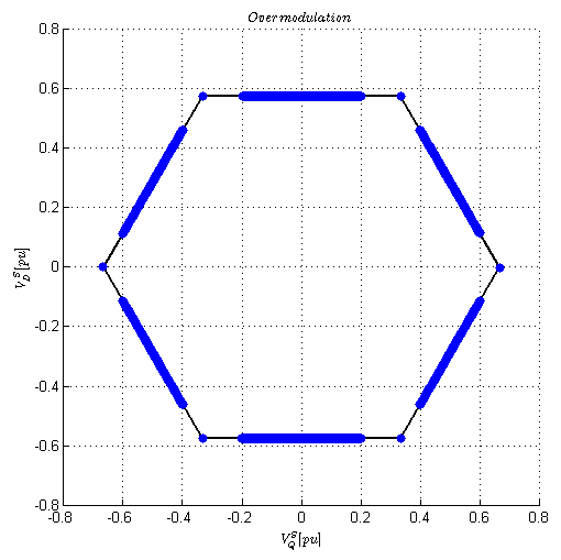
In any case, we have put together a representative example of a 2-level voltage modulator with a basic 3rd harmonic injection and simplistic duty ratio limitation (0 to 1). The figures below also show the 2-phase equivalent voltage vector (Valpha/Vbeta for non-WEMPECers and stationary QD for WEMPECERs :) ) and 3-phase output voltages for linear modulation and several overmodulation cases. The DC link voltage is 24 V.
Phase voltage reference: 8 V peak
Phase voltage reference: 12 V peak (maximum linear modulation without 3rd harmonic injection)
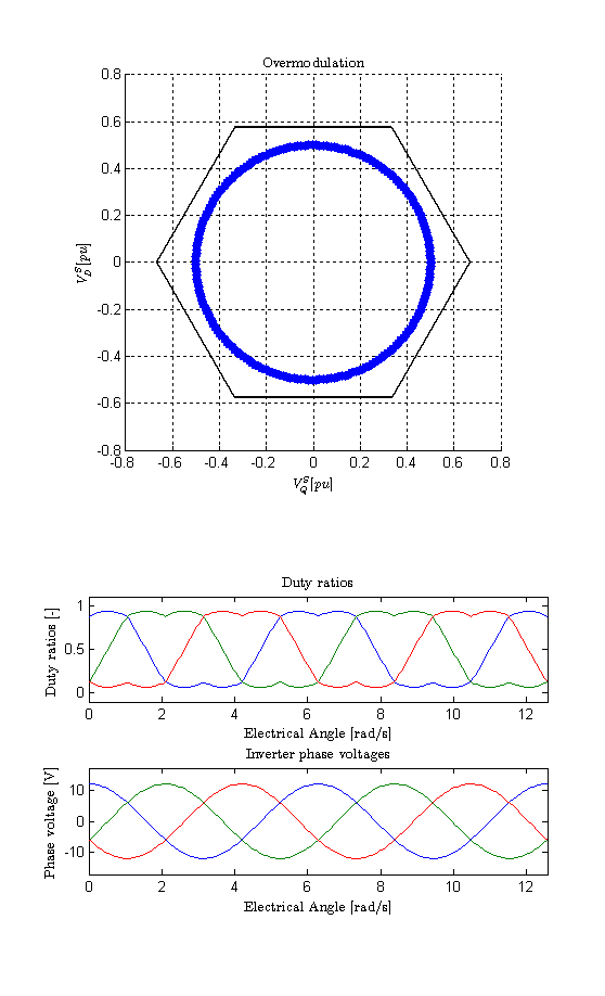
Phase voltage reference: 13.85 V peak (maximum linear modulation with 3rd harmonic injection)
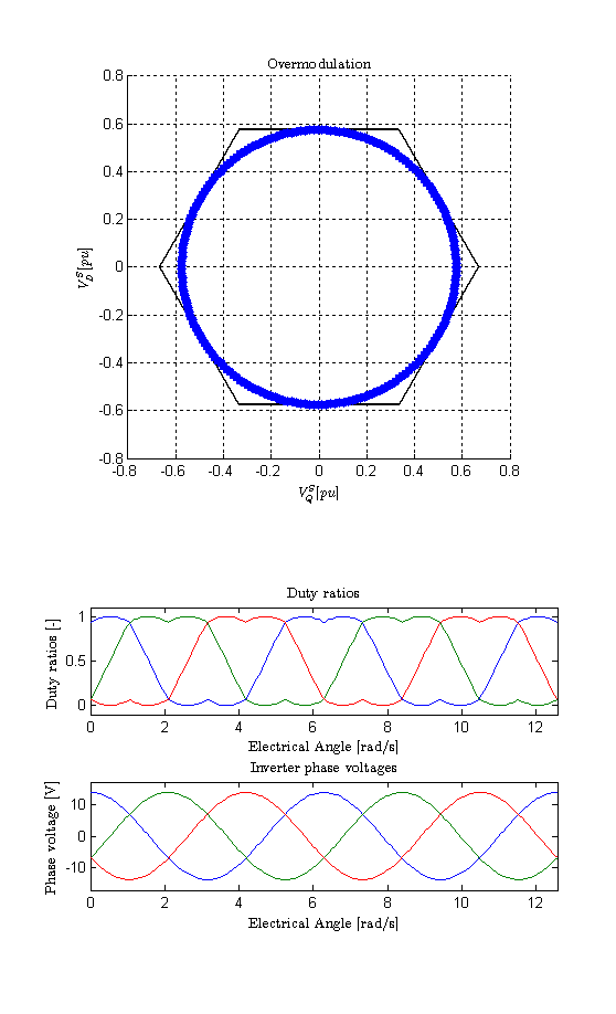
Phase voltage reference: 14.2 V peak (slight overmodulation)
Phase voltage reference: 15 V peak (major overmodulation)
Phase voltage reference: 17 V peak (total overmodulation, the fundamental is not realizable since 17 V > 24 V * 2/pi (= 15.27 V).
% Standard Overmodulation Script
%
% Tomas Sadilek, 12/25/2014
%
% This script shows the basic overmodulation waveforms for a three-phase
% voltage-source inverter.

% clean up
clear all; clc; format compact;

% Definitions
Vdc = 24 % DC bus voltage
Vout_mag = 8 % Output phase voltage

% Angle vector, 2 cycles
theta = linspace(0,4*pi,200);
Valpha = Vout_mag * cos(theta);
Vbeta = Vout_mag * sin(theta);

% Valpha and Vbeta are the outputs of our current regulator
v_a_out = Valpha;
v_b_out = -Valpha/2 + sqrt(3)/2 * Vbeta;
v_c_out = -Valpha/2 - sqrt(3)/2 * Vbeta;

da = v_a_out/Vdc + 0.5;
db = v_b_out/Vdc + 0.5;
dc = v_c_out/Vdc + 0.5;

% // determine min and max
dmax = max(max(da,db),dc);
dmin = min(min(da,db),dc);

% // Regular SVM
d0 = 0.5 - 0.5*dmin - 0.5*dmax;

da = da+ d0;
db = db + d0;
dc = dc + d0;

% Limit the duty ratios
da(da > 1) = 1; da(da < 0) = 0;
db(db > 1) = 1; db(db < 0) = 0;
dc(dc > 1) = 1; dc(dc < 0) = 0;

% === Recalculate Valpha and Vbeta and phase voltages
dn = (da+db+dc)/3;
va = Vdc*(da-dn);
vb = Vdc*(db-dn);
vc = Vdc*(dc-dn);

Valpha_out = va;
Vbeta_out = 1/sqrt(3)*(vb-vc);

figure(1)
hold off
clf
set(gcf,'color','w');
subplot(4,1,1:2)
svm_alpha = [1 0.5 -0.5 -1 -0.5 0.5 1]*.667;
svm_beta = [0 1 1 0 -1 -1 0]*sqrt(3)/2*.667;
hold on
for k=1:6,
line([svm_alpha(k) svm_alpha(k+1)],[svm_beta(k) svm_beta(k+1)],'color','black','linewidth',2)
end

% Plot output - blue
plot(Valpha_out/Vdc,Vbeta_out/Vdc,'linestyle','--','marker','.','markersize',20,'Color','red')
% Plot reference - red
plot(Valpha/Vdc,Vbeta/Vdc,'linestyle','none','marker','.','markersize',20,'Color','blue')
axis([-0.8 0.8 -0.8 0.8])
grid on
hold off
title('Overmodulation','Interpreter','LaTex')
ylabel('$V_D^S [pu]$','Interpreter','LaTex')
xlabel('$V_Q^S [pu]$','Interpreter','LaTex')
axis('square')

subplot(5,1,4)
plot(theta,da,theta,db,theta,dc)
axis([-inf inf -0.1 1.1])
title('Duty ratios','Interpreter','LaTex')
xlabel('Electrical Angle [rad/s]','Interpreter','LaTex')
ylabel('Duty ratios [-]','Interpreter','LaTex')

subplot(5,1,5)
plot(theta,va,theta,vb,theta,vc)
axis([-inf inf -Vdc/1.4 Vdc/1.4])
title('Inverter phase voltages','Interpreter','LaTex')
xlabel('Electrical Angle [rad/s]','Interpreter','LaTex')
ylabel('Phase voltage [V]','Interpreter','LaTex')

img = getframe(gcf);
FileName = strcat(['V',num2str(Vout_mag)])
imwrite(img.cdata, [FileName, '.png']);

% === no more
Further Reading
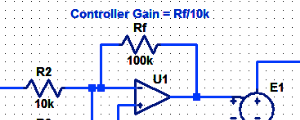
Proportional Controller Implementation
In MatLab, DSPs, and FPGAs.
.
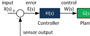
Control System Block Diagram
The fundamentals of signal flow.
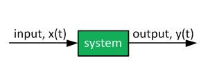
System Modeling With Transfer Functions
Introduction to dynamic systems.
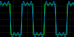
Fourier Series Demo
It is all sine waves.